Overview
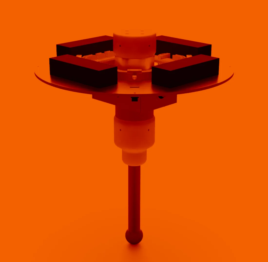
I designed and built Monopod from the ground up, right down to the voice coil actuator that drives its leg. And it jumps.
I used Fusion 360 for the mechanics and PCB, C++ for the microcontroller code and Python for the actuator analysis.
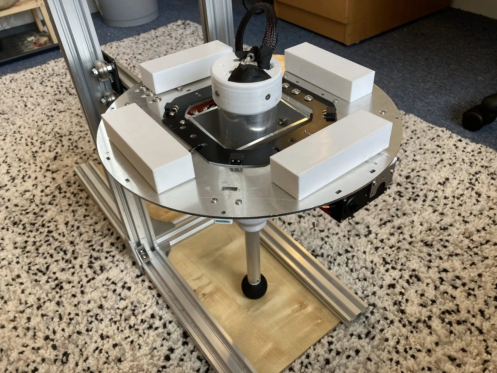
The requirements:
- One leg that can jump (read: more than once)
- Untethered (battery powered)
After reading research papers on similar robots, I settled on an inverted pendulum design driven by a voice coil actuator (VCA).
The Actuator
Actuating the prismatic joint was one of the project's biggest challenges. A VCA suits it well because:
- It is compliant both in operation and on standby
- An uncommutated VCA is simple to control (a single H-bridge)
- It is relatively simple to build
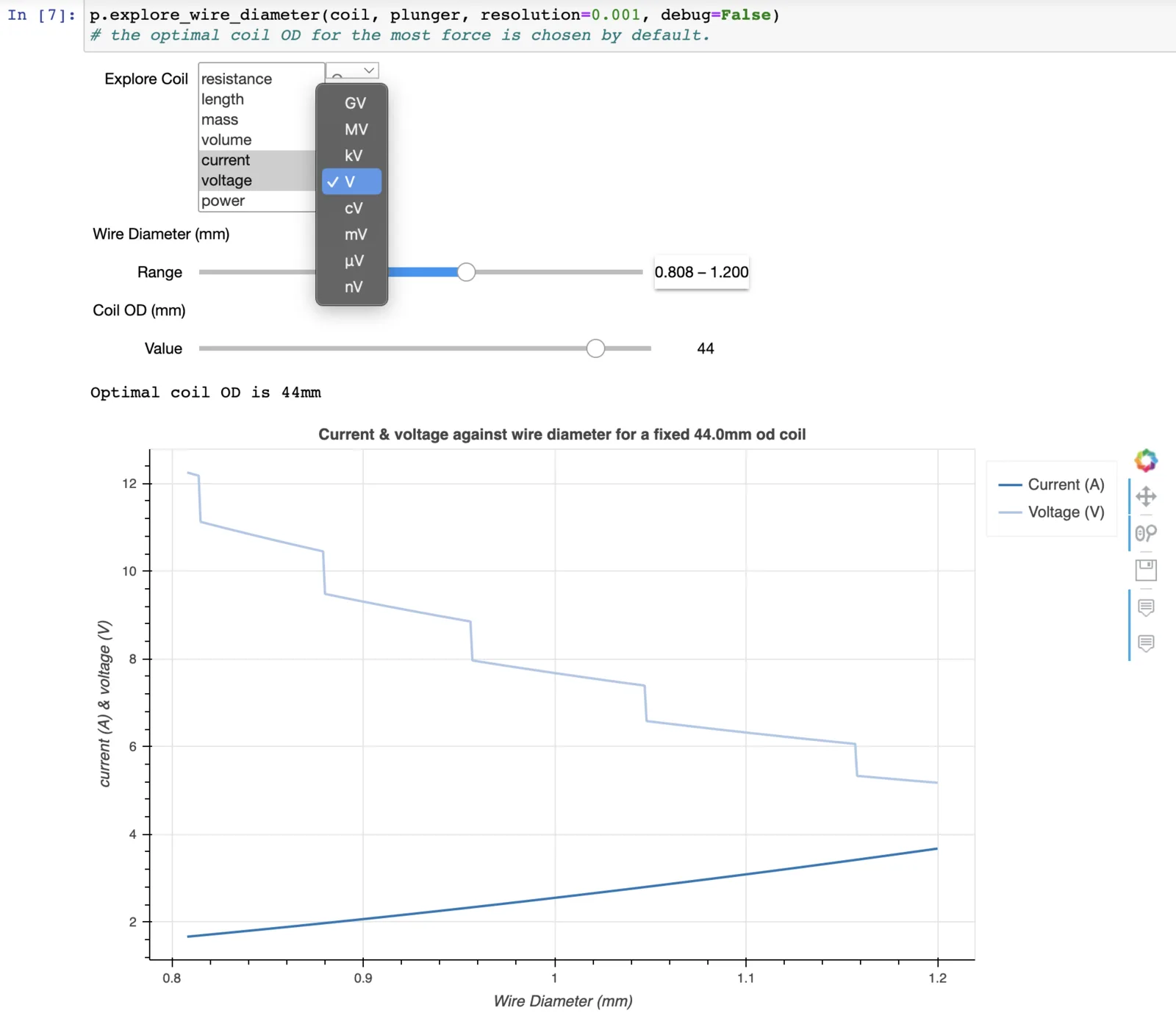
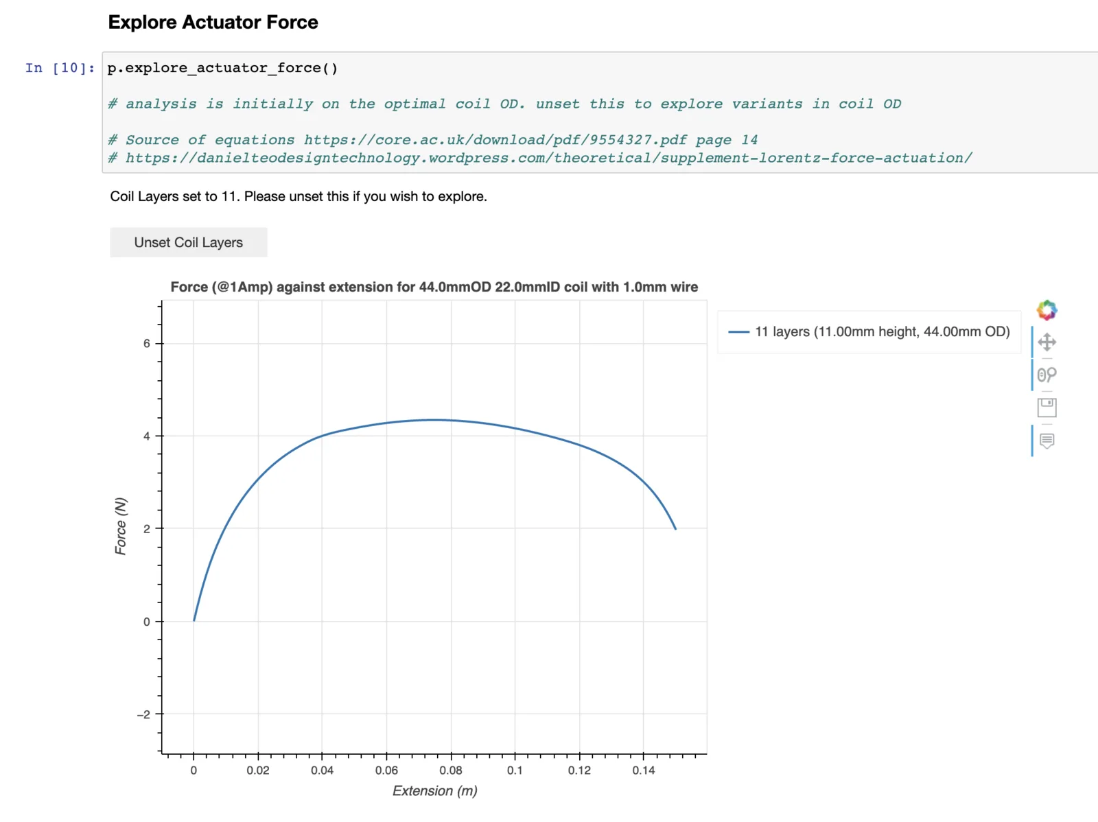
After contacting the 3-4 companies that make VCAs commercially, I realised cost left me one option: build my own. I started with a Jupyter notebook to analyse the VCA. This is crucial, since a coil's performance depends on many parameters: coil dimensions, wire diameter, applied voltage and more.
Show graphs from the notebook
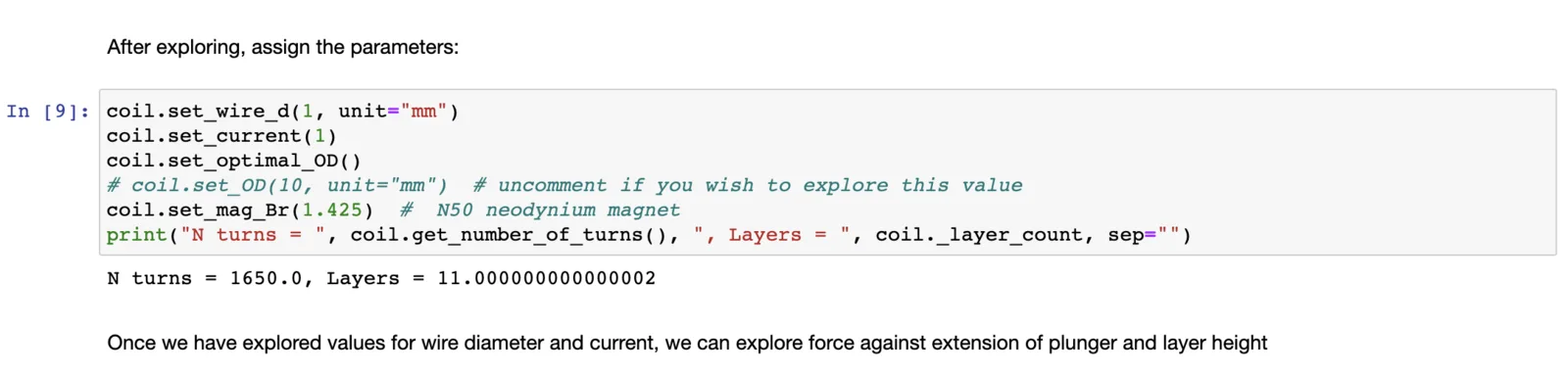
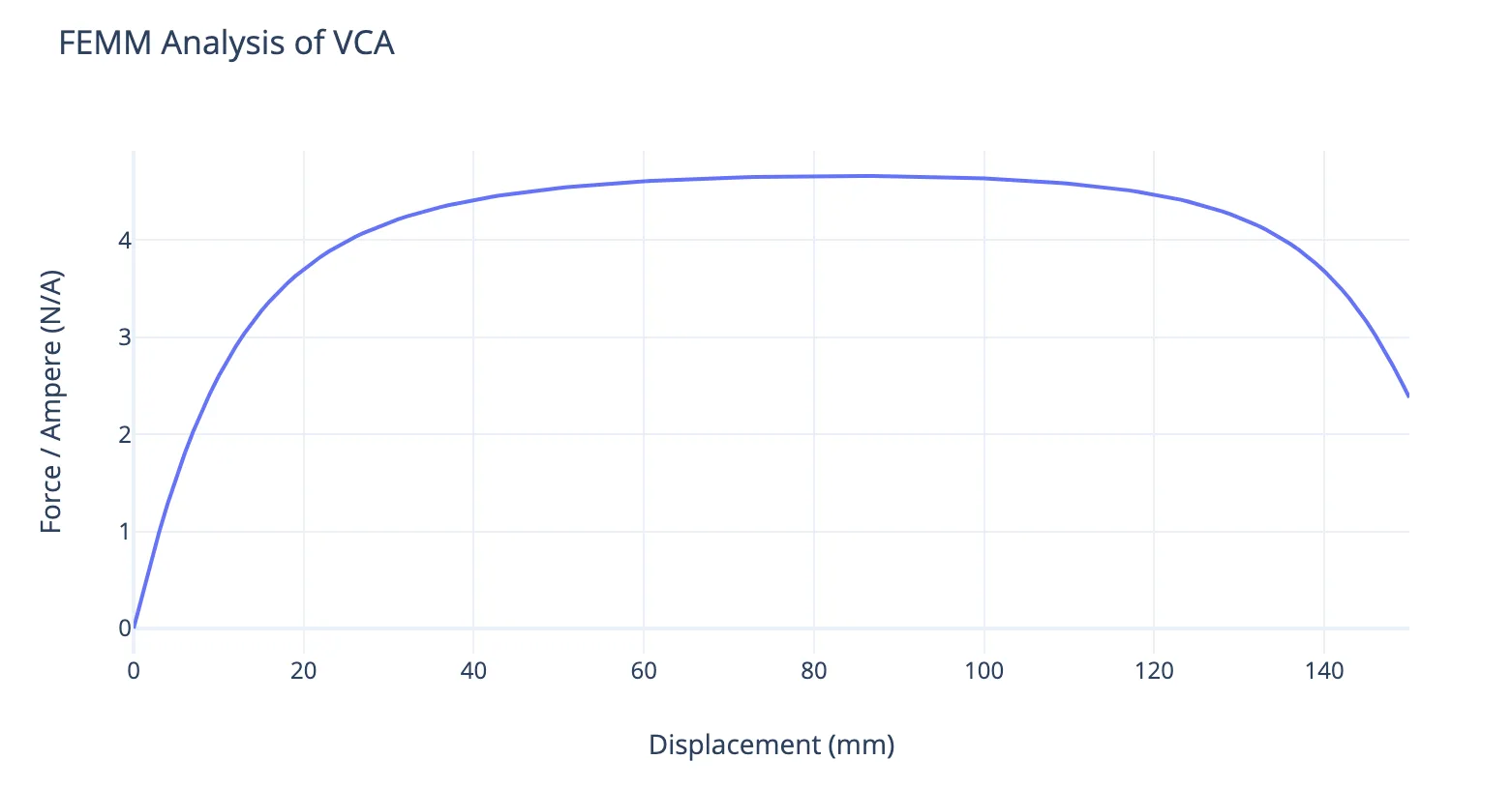
I then verified the chosen coil design with an FEMM simulation.
Making the Coil
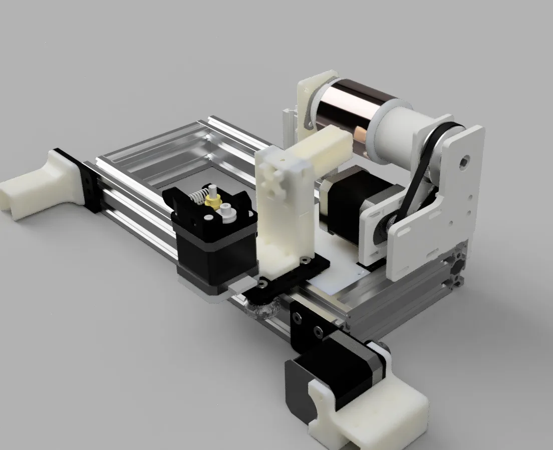
To manufacture the coil, I designed...
Show a render (if the interactive model doesn't load)
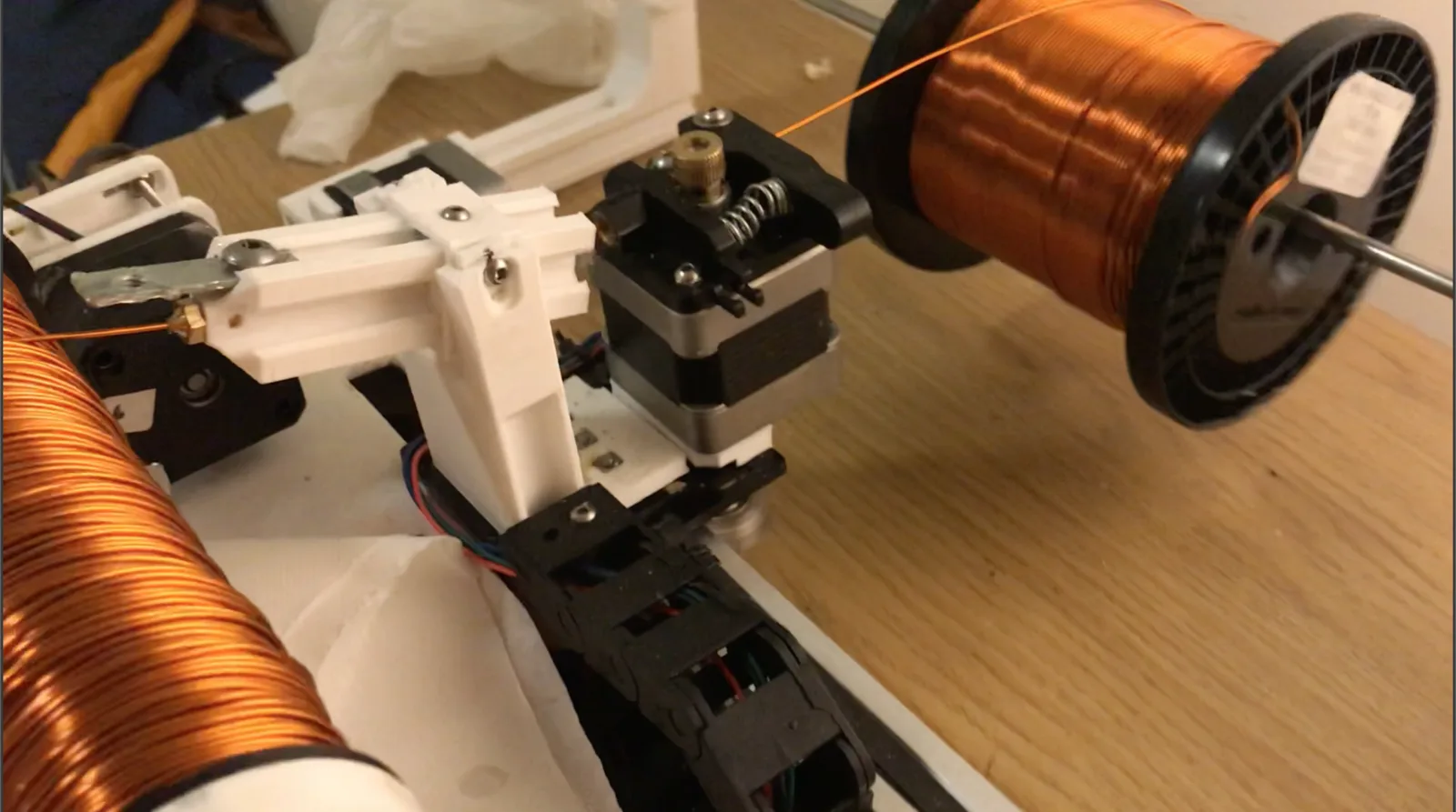
... and built ...
The Robot
With the coil done, I designed the robot itself.
Show renders (if the interactive model doesn't load)
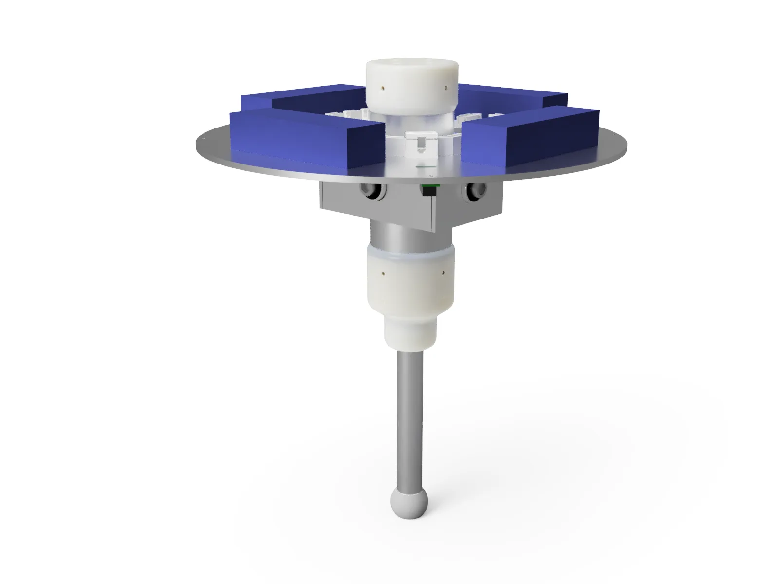
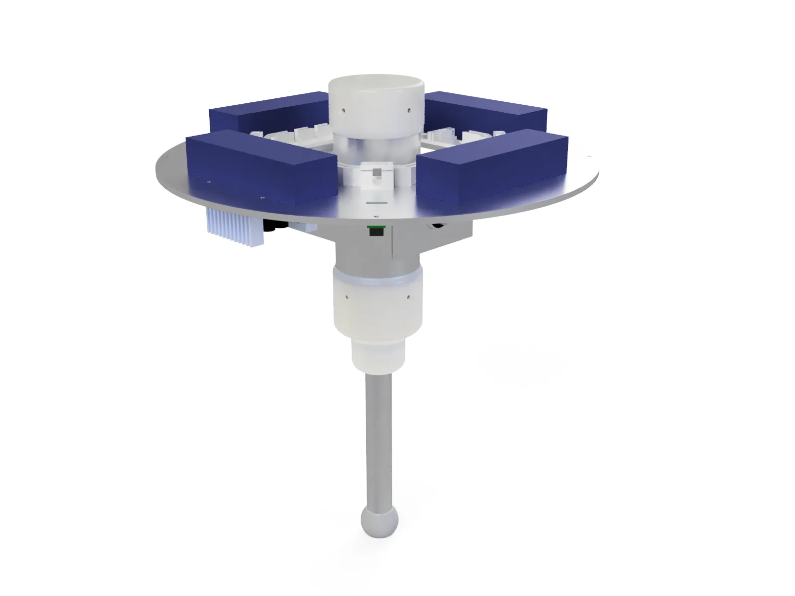
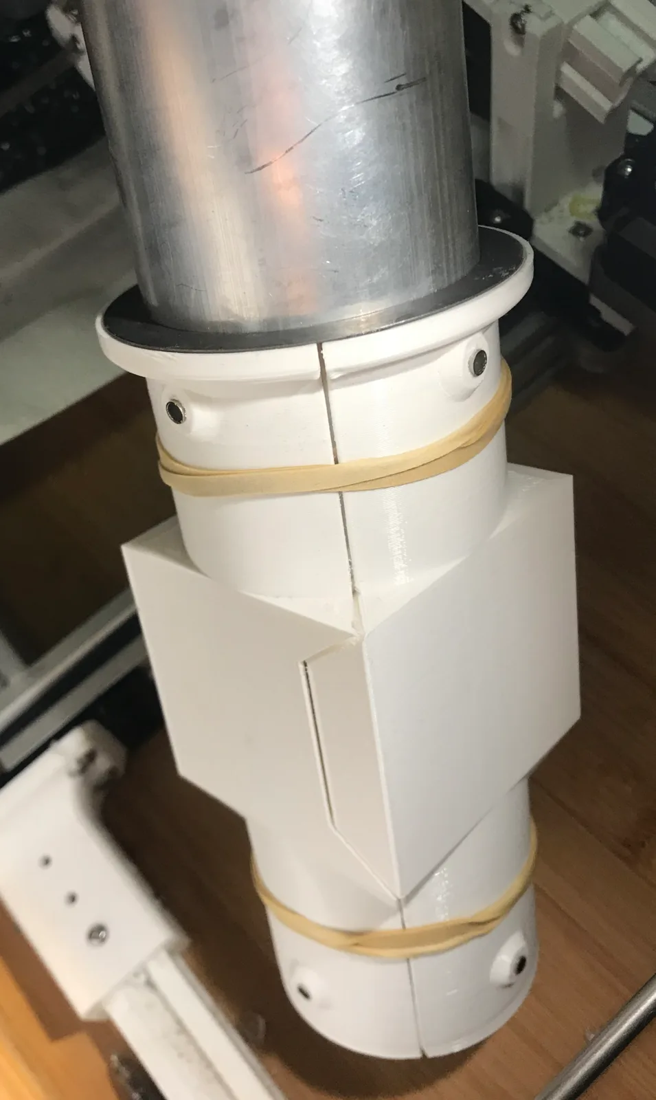
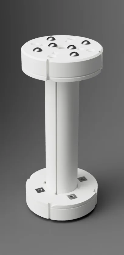
The trickiest part was the rotationally constrained spring-plunger that houses the magnets. Ferrous materials can't sit near the VCA, which ruled out traditional linear bearings and steel shafts. Instead I used Igus polymer bearings, which can also be 3D printed in Igus' own filament. In version 2, I will use this to integrate the bearing into the coil and remove the bearing housing at the bottom entirely.
For the foot, I took inspiration from Ben Katz (MIT Biomimetics) and Josh Pieper, casting it from Smooth-On FlexFoam-iT! 17 in a squash-ball-esque fashion.
For the leg's 2-axis joint, I first looked at Dynamixel's MX-106T Dual Axis Robot Joint, but at $1.2k it was over budget. Instead I designed a 2-axis gimbal that sits inside the body rather than below it, which reduces the leg's inertia. Its two axes of rotation are coincident, and the centre of mass lies on their intersection.
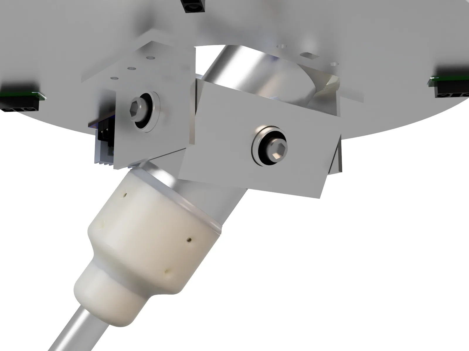
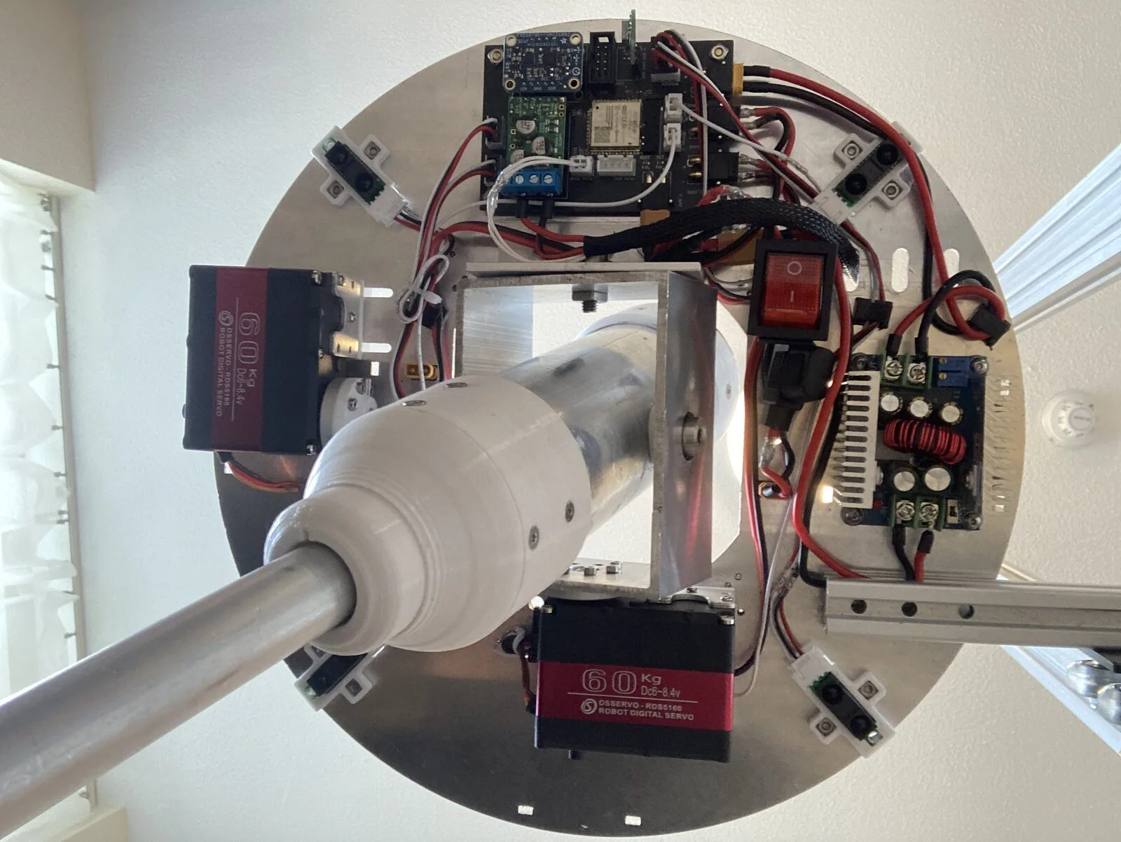
To make the many custom parts accurately, I 3D printed jigs that precisely locate features such as tapped holes. I used them to make the carbon fibre plunger, the aluminium casing tube and the VCA coil.
Electronics
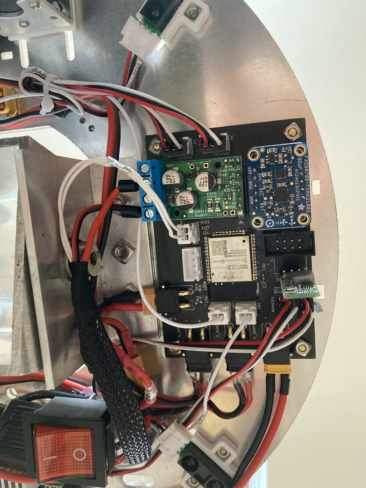
The electronics needed:
- 4 distance sensors to measure the body's angle to the ground (one is redundant)
- An IMU with a very accurate gyro, also for the body's angle
- An H-bridge for the VCA, with current and temperature sensing
- 7.2V and 3.3V power distribution from the batteries
- Wi-Fi for control and logging
- A linear quadrature encoder for the VCA
- Vibration-proof power and logic connectors
With these in mind, I designed the PCB:
Result
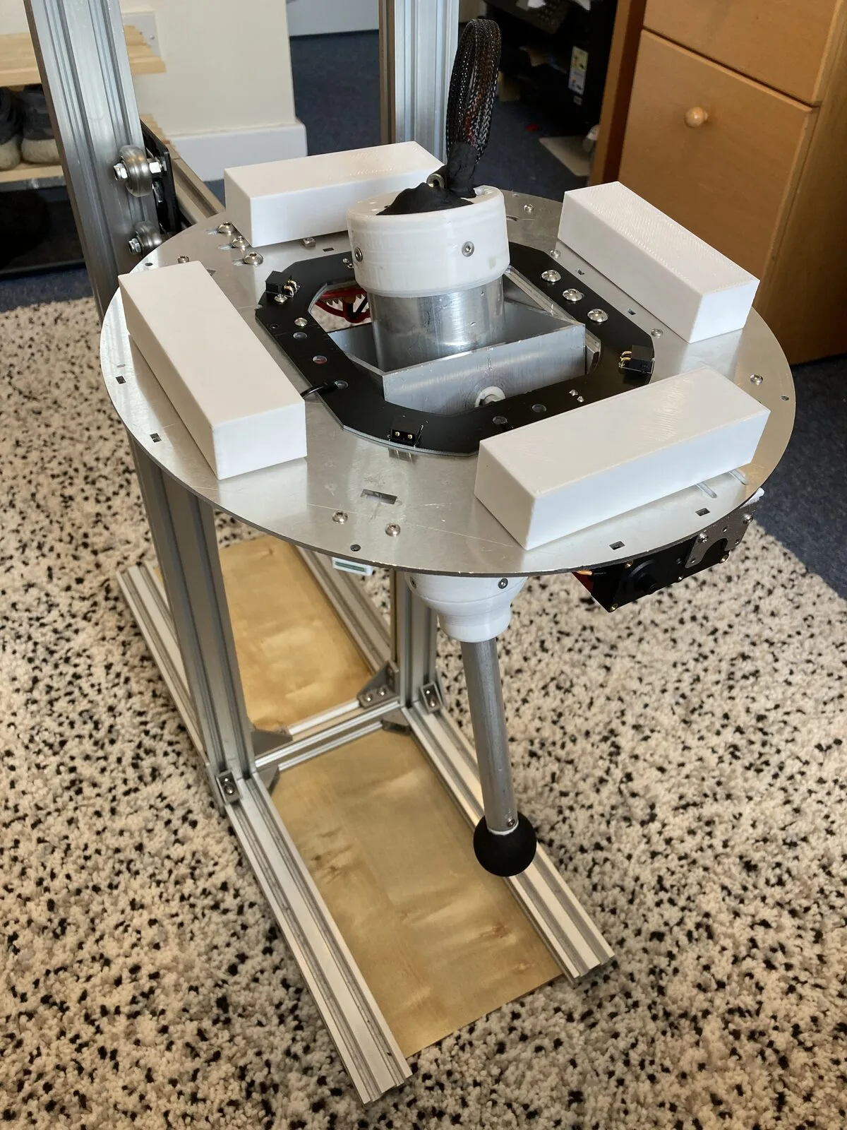
With the robot built and jumping, the next step is to simulate it in PyBullet and use the simulation to generate gaits. Thanks for reading! :)
← Other Projects